Indications & Contraindications
Indications
- Sacral insufficiency fractures (most common indication) — Denis Zone I (alar), Zone II (foraminal), Zone III (central body)
- Osteoporotic insufficiency fractures — postmenopausal women, long-term steroid use, low BMD
- Radiation-induced insufficiency fractures — after pelvic or cervical cancer radiotherapy; 21–34% prevalence in irradiated patients
- Pathologic fractures — metastatic disease, myeloma (combined with ablation as needed)
- Failure of conservative management (≥4–6 weeks): pain control, bed rest, progressive weight-bearing inadequate
Contraindications
- Active infection (sacral osteomyelitis, discitis, surrounding soft tissue infection)
- Sacral tumor without concurrent ablation plan
- Fracture with retropulsion causing neurologic deficit — requires surgical decompression first
- Uncorrectable coagulopathy
- Unstable fracture with spino-pelvic dissociation requiring surgical fixation
- Patient unable to tolerate prone positioning
Denis Zone Classification
| Zone | Location | Frequency | Neurologic Risk | Sacroplasty |
|---|---|---|---|---|
| Zone I | Sacral alar (lateral to foramina) | 50% (most common) | Low (L5 root at risk) | Ideal — long-axis approach |
| Zone II | Sacral foramina (S1–S4) | 34% | 28% neurologic deficit | High risk — CT guidance mandatory; extreme caution |
| Zone III | Central sacral body / spinal canal | 16% (least common) | 58% neurologic deficit | Very rare indication; surgical consultation |
H-fracture (Honda sign): bilateral vertical Zone I fractures connected by horizontal Zone III fracture — classic osteoporotic pattern; bilateral sacroplasty required.
Pre-Procedure Planning
Imaging Requirements
- MRI sacrum with STIR sequence: STIR hyperintensity = bone marrow edema = active fracture = treat now. No STIR edema = old/healed fracture = no benefit from sacroplasty
- CT sacrum: fracture morphology, Denis zone mapping, foraminal anatomy, trajectory planning (multiplanar reformats)
- MRI also identifies: retropulsion, epidural tumor, neural foraminal compromise (all may alter management)
- Bone scan (SPECT-CT): if MRI unavailable or contraindicated; H-sign = bilateral Zone I fractures on nuclear medicine
- Plain radiographs: low sensitivity (20–38%); multiple views required; CT preferred
Labs & Patient Prep
- CBC, PT/INR (INR ≤1.5), platelets ≥50K
- Bone density (DEXA) — obtain if not recent; post-procedure osteoporosis management planning
- NPO 4–6h (MAC sedation)
- IV access; blood pressure monitoring
- Fluoroscopy suite or CT suite setup — biplanar fluoroscopy strongly preferred for cement injection monitoring
- Cement batch prepared and tested prior to starting (PMMA viscosity and working time are temperature-dependent)
Relevant Anatomy
Sacral Structure & Nerve Roots
- Sacrum: main stabilizer of posterior pelvic wall; transmits axial loads from trunk to lower limbs; protects lumbosacral plexus and iliac vessels
- S1 nerve root: exits through S1 foramen (foraminal zone); most at risk from Zone II fractures and cement leak
- S2–S4 nerve roots: sacral parasympathetic fibers; injury = bowel/bladder dysfunction
- Sacral foramina (anterior and posterior): S1–S4 nerve roots exit; must be identified and avoided on pre-procedure CT
- Iliac vessels: medially adjacent to sacral ala; course identified on CT to plan safe Zone I approach
Needle Access Approaches
- Long-axis (caudo-cephalic): standard preferred approach; needle inserted in cauda-to-cephalad direction along Zone I alar axis; allows complete fracture line filling; developed by Smith & Dix 2006
- Short-axis (posterior-anterior): older technique; less predictable intramedullary placement; higher cement extravasation rate; largely replaced by long-axis
- Transiliac approach: needle through iliac bone traversing SI joint; alternative for difficult access; rarely used
- Long-axis approach: needle enters through posterior sacral surface, angled medial-lateral and caudo-cranially into the alar intramedullary space, staying lateral to S1 foramen
Supplies & Setup
Bone Access
- 11G or 13G vertebroplasty trocar (e.g., Cook Osteo-Site, Stryker) — 10–15 cm working length
- Standard spinal needle (25G) for skin and periosteal local anesthesia
- Mallet for trocar advancement into sacral bone (11G requires mallet; 13G may be hand-advanced)
- Extension tubing for cement injection syringe
Cement System
- High-viscosity PMMA cement: Kyphon, Confidence, or equivalent radiopaque formulation
- 10 mL bone cement syringe
- Cement mixing system per manufacturer protocol
- Target volume: 2–4 mL per Zone I alar fracture (2–8 mL range per literature); bilateral = 4–8 mL total
- Saline flush (10 mL) to create interosseous venogram before cementing
Imaging & Medications
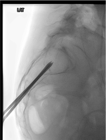
- Fluoroscopy suite (biplanar preferred: AP + lateral simultaneously) OR CT fluoroscopy
- Iodinated contrast for interosseous venogram (identifies extravasation risk)
- Lidocaine 1% + bupivacaine 0.5% (Marcaine): skin, subcutaneous, and periosteum infiltration (10 mL Marcaine for periosteal elevation)
- MAC sedation medications: propofol, fentanyl, midazolam per anesthesia
- Toradol 30 mg IV (post-procedure pain) + ondansetron 4 mg IV
Procedure Steps
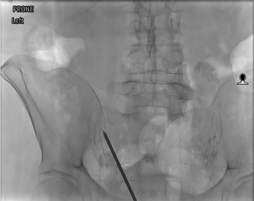
Prone Positioning & CT/Fluoro Planning
Local Anesthesia & Periosteal Elevation
Trocar Insertion — Long-Axis Technique
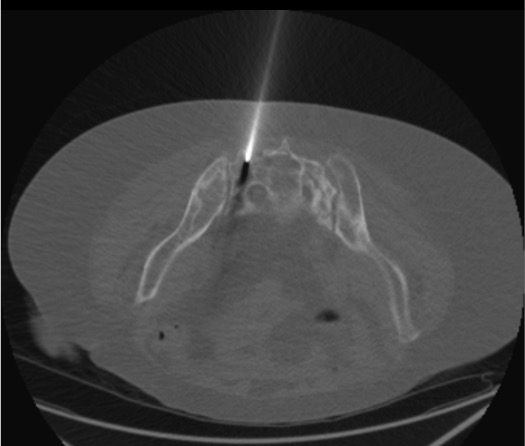
Biplanar Fluoroscopic or CT Confirmation of Trocar Position
Interosseous Venogram
PMMA Cement Injection
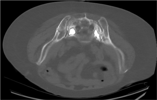
Contralateral Side (Bilateral for H-Fracture)
Trocar Removal & Post-Procedure Assessment
Community Cards
Troubleshooting
Cement Appears to Track Toward S1–S4 Foramina on Fluoroscopy
Stop injection immediately. Wait for cement to harden (2–3 min). Obtain CT to assess exact location and relationship to foramina. If cement is in the foramen: assess neurologic function; if deficit present, urgent decompression consultation. If cement is approaching but has not entered foramen and patient is asymptomatic: cease injection on that side, address contralateral if needed. Do NOT continue injecting in hope cement will redirect away from foramina.
Patient Reports Radicular Pain or New Numbness During Cement Injection
Stop cement injection immediately. This is the critical clinical signal for foraminal cement leak or nerve root thermal injury from exothermic PMMA curing reaction. Obtain CT immediately. Assess for foraminal cement. If symptoms persist post-procedure: orthopedic or neurosurgery consultation urgently for possible decompression. Incidence of surgical decompression requirement: 0.3%.
Trocar Appears to Be in Cortical Bone or Extraosseous on CT
Do not inject cement. Partially withdraw trocar under CT guidance. Redirect using adjusted medial-lateral and caudo-cranial angle. Confirm intramedullary position with CT before proceeding. The long-axis technique requires accurate angling — initial entry angle is the most critical step; small angular errors compound over the length of the alar.
Cement Consistency Is Too Thin at Time of Injection
Wait for cement to polymerize to "toothpaste" consistency before injecting. Test consistency by extruding a small amount on the sterile field — it should hold its shape when pressed. Too-liquid cement risks: rapid venous migration, pulmonary embolism, and uncontrolled spread to foramina. If cement has already hardened beyond injectable viscosity: abort injection for that trocar; clinical outcomes acceptable with partial fracture fill in most cases.
Complications
Cement-Related Complications
- Sacral nerve root injury — cement in foramina; S1 = foot drop; S2–S4 = bowel/bladder dysfunction; most serious complication; requires urgent decompression if symptomatic
- Cement into SI joint — may cause chronic pain; usually asymptomatic; avoid by maintaining medial to SI joint on fluoroscopy
- Venous cement embolism — rare but potentially fatal; pulmonary embolism from IV injection of liquid cement; prevention: toothpaste consistency, slow injection, stop at any venous runoff
- Cement extravasation through posterior cortex — usually asymptomatic; rarely causes pain at entry site
General Complications
- Infection / osteomyelitis — rare with percutaneous technique; sterile prep mandatory; foreign body (PMMA) perpetuates infection if it occurs
- Further sacral fracture — underlying osteoporotic bone; contralateral fracture from altered load transfer; address with bilateral sacroplasty and bone density treatment
- Incomplete pain relief — usually from incomplete fracture fill or untreated contralateral fracture; reassess imaging
- Cement leakage rate — up to 55% with standard technique; reduced to 22% with balloon-assisted (balloon sacroplasty) technique
Post-Procedure Care & Pearls
Recovery & Discharge
- Motor exam immediately post-procedure: confirm no new lower extremity weakness or sensory deficit before discharge
- Ambulate 1–2h post-procedure with assistance; most patients ambulate day of procedure
- Pain response: 24–72h for initial response; 90% of patients report pain reduction at 1 year (Frey et al 2008)
- Protective brace: some centers recommend for up to 3 months; patient and surgeon preference
- Discharge same day for most patients; overnight for elderly patients with monitoring needs
Follow-up
- Pain score at 24–48h (call or clinic): expected VAS reduction from ~8/10 to ~3.5/10
- Plain radiograph at 1 month: confirm cement position, no hardware failure
- Bone density (DEXA): if not already on treatment → bisphosphonate or denosumab therapy; essential for fracture prevention
- Assess for contralateral fracture at follow-up (Honda sign; bilateral fracture common)
- Full spine assessment: lateral spine films and DEXA; concurrent vertebral compression fractures common in this population
Technique Pearls
Critical Pitfalls
References & Resources
Sacroplasty vs Vertebroplasty
| Feature | Vertebroplasty | Sacroplasty |
|---|---|---|
| Target bone | Vertebral body | Sacral alar (Zone I) |
| Primary risk | Cement into spinal canal / disc | Cement into sacral foramina / SI joint |
| Guidance | Biplanar fluoroscopy (standard) | CT preferred (especially Zone II) |
| Trocar size | 10–13G | 11–13G |
| Cement volume | 2–6 mL per vertebra | 2–4 mL per Zone I alar (bilateral) |
| Pain response timeline | 24–72h | 24–72h (VAS 8.3 → 3.6 at 24–48h) |
Primary References
- Prologo JD, Ray CE Jr., eds. Advanced Pain Management in Interventional Radiology: A Case-Based Approach. Thieme; 2024. DOI: 10.1055/b000000387
- Chandra V, Wajswol E, Shukla P, Contractor S, Kumar A. Safety and efficacy of sacroplasty for sacral fractures: a systematic review and meta-analysis. J Vasc Interv Radiol. 2019;30(11):1845–1854. [Meta-analysis, 19 studies: significant VAS reduction at 24–48h, 6 months, 12 months; major complications 0.3%]
- Frey ME, DePalma MJ, Cifu DX, et al. Percutaneous sacroplasty for osteoporotic sacral insufficiency fractures: a prospective, multicenter, observational pilot study. Spine J. 2008;8(2):367–373.
- Frey ME, Warner C, Thomas SM, et al. Sacroplasty: a ten-year analysis of prospective patients. Pain Physician. 2017;20(7):E1063–E1072. [90% pain reduction at 1 year]
- Smith DK, Dix JE. Percutaneous sacroplasty: long-axis injection technique. AJR Am J Roentgenol. 2006;186(5):1252–1255. [Original long-axis technique description]
- Denis F, Davis S, Comfort T. Sacral fractures: an important problem. Retrospective analysis of 236 cases. Clin Orthop Relat Res. 1988;227:67–81. [Denis Zone classification]
- Lyders EM, Whitlow CT, Baker MD, Morris PP. Imaging and treatment of sacral insufficiency fractures. AJNR Am J Neuroradiol. 2010;31(2):201–210.